Application of RS393 in Lithium Battery Charging Thermal Management System
 2022-01-27
This article takes RS393 as an example to explain how to apply the window comparison circuit to the lithium battery charging temperature control circuit. Analyze the working principle of the window comparator and the calculation in the hysteresis circuit.
The main parameters of RS393:
●Power supply range: +1.8V to +5.5V;
●Low quiescent current Vs = 5V, 50μA/ch (TYP);
●Input common mode voltage range: (V-)-0.1V to (V+)+0.1V;
●Low output saturation voltage: 150mV (TYP);
●Group delay (H to L@5V): 185ns;
●Open drain output.
Necessity of temperature control in lithium battery charging circuit
When the temperature in the environment is low, the actual available capacity of the battery will rapidly decay. If the temperature is too low (such as lower than 0°C), charging the lithium battery may cause an instantaneous voltage overshoot, causing an internal short circuit. Overheating of the battery may cause accidents such as smoke, fire or even explosion.
The most suitable charging temperature for the battery is between 10°C and 30°C. Too high or too low temperature will cause the battery life to decay quickly. Only by accurately measuring the ambient temperature of the battery can the battery be preheated and dissipated in low and high temperature environments.
The design of temperature control circuit
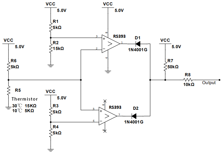
The window comparator built by RS393 is used to detect the temperature of the lithium battery:

Figure 1 Window comparison circuit
The temperature of the lithium battery is obtained by PTC (Positive Temperature Coefficient Thermistor). For the convenience of calculation, it is assumed that the resistance of the thermistor at 10°C is 15KΩ, and the resistance at 30°C is 5KΩ. Connect the input and output of the two comparator circuits in the figure in parallel. When the input signal is less than 2.5V or greater than 3.75V, the circuit outputs a low level; when the input signal is between 2.5V and 3.75V, the circuit outputs a high level, which constitutes a window comparator.
Design and necessity analysis of hysteresis window comparison circuit
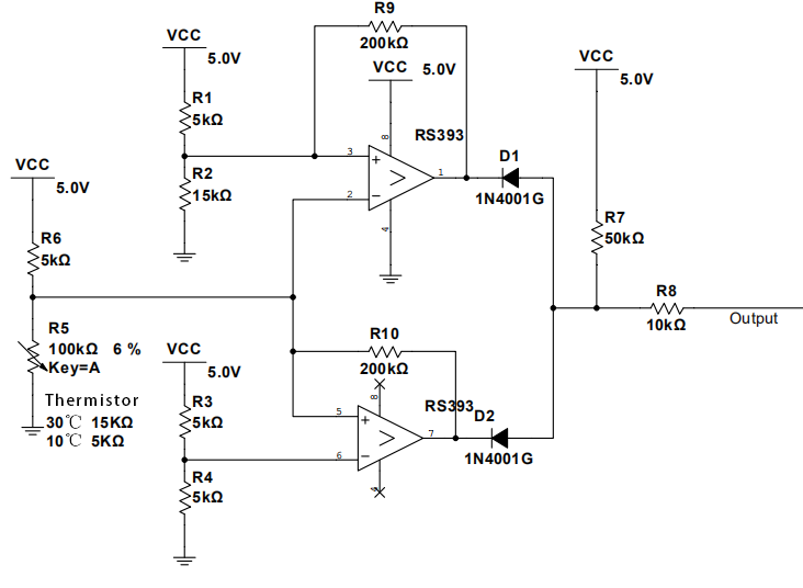
In the circuit connection of Figure 1, when the input signal of the comparator slowly approaches the positive/negative gate level, the interference pulse superimposed on the signal is very likely to cause the output to be reversed incorrectly, leading to misjudgment. In this regard, the hysteresis circuit is an optimal solution. Figure 2 shows the hysteresis window comparison circuit after adding a positive feedback resistor.

Figure 2 Hysteresis window comparison circuit
Use the node voltage method to analyze the input and output voltage nodes of the comparator respectively. The upper threshold voltages Vupp and Vupn of the window comparator are obtained; the lower threshold voltages Vdown and Vdownn are obtained. Taking the PTC thermistor with positive temperature coefficient as an example, the corresponding relationship between voltage and temperature of different thresholds is shown in the following table:
Voltage value |
Temperature value |
|
Vupp |
3.75V |
30℃ |
Vupn |
3.54V |
25℃ |
Vdownp |
2.93V |
15℃ |
Vdownn |
2.48V |
10℃ |
Table 1 Correspondence between different threshold voltage and temperature
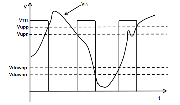
The simulation waveform of the hysteresis window comparison circuit is as follows:

Figure 3 Waveform diagram of hysteresis window comparison circuit
It can be seen from Figure 3 that by adding a window comparator circuit after hysteresis, the interference of the ringing phenomenon on the circuit output can be avoided.


